Buckle up, this is a big one
You’ve probably heard of the video game PONG

If you haven’t noticed from my other projects, I’m a big fan of robots and CNC-type machines. So naturally, I thought it would be pretty cool to make a CNC version of this video game classic.
I imagined it like this: two players will have one wireless controller each. With these, they would be able to move ‘paddles’ up an down, which in reality would be belt driven carriages lit by WS2812b individually addressable LEDs. The ‘ball’ would be another LED lit belt driven carriage, but in this case it would move in 2 dimensions in the plane of the paddles. The collisions of the ball with the walls and the paddles along with the trajectory of the ball will be calculated in software and visual feedback of the collision would be shown to the players using a border of more individually addressable LEDs. That is, there would be no actual bouncing of the ball off the walls and paddles- it would simply appear that way to the players.
Essentially, this would simply be a mechanical CNC version of the original game, with similar mechanics and playability.
Things on This Page
Player Controllers
I decided to start with the easiest part of the build- the two wireless player controllers.
Hardware Construction
Rather than design the handheld controllers completely from scratch, I opted to use Nintendo Wii Nunchucks. This has been my go-to controller for several other projects, and it was perfect for this application, since it featured a 2-axis joystick and two buttons, plenty of control surfaces for the player to move their paddles, choose game modes, and change paddle colors .

These were non-original Nunchucks (no pint paying extra for OEM) so the first step was to take them apart and see what I had to work with.
I first dealt the casing. I had to fit a lot of electronics in here, and the original controller casing didn’t have much room for much other than the original circuit board and cable.

I removed some of the support ribs and the crew standoffs from the bottom half of the controller using a rotary tool with a little carbide burr. This cleared up quite a bit of space without compromising the structural integrity of the controller. Since the screw standoff was now missing, I had to find a different way to secure the two halves of the controller when I put it back together later.

Then there were the nunchuck electronics. Inside the body of the controller is this little circuit board, onto which is mounted two buttons, the joystick, and a potted IC that I guess does some processing onboard. The wire harness that connects to the board leads out of the controller and to the wii remote connector.

Fortunately for me, the designer of this board was very informative with their silk-screening, and I found out that the nuchucks transmit their data over I2C as indicated by the words ‘SDA’ and ‘SCL’ printed on the board. This meant I can read the joystick and button values with only two pins on my arduino.

Of course there already existed several arduino libraries for reading I2C data from a nunchuck, so I just picked a random one, which I’ve linked here. From the readme page, I found out that the Wii nunchucks also featured a 3 axis accelerometer (if you remeber playing Boxing on Wii Sports, this is what allowed you to throw punches with your nunchuck hand) but this data wasn’t really useful for my application.
I cut a piece of the original cable and used its wires to break out VCC, SDA,SCL, and GND from this board.

Now that I had a source of data, I needed a way to read it and send it wireless to do the main PONG controller. To accomplish the former, I used this tiny arduino board, which features the same microcontroller as the Leonardo/Micro (the ATMEGA32u4) and a 3.3v regulator on a very minimal board.
Fun fact- the ATMEGA32u4 has the unique feature of being able to act as a USB HID device, so people often use these boards for custom keyboards, Launchpad-type music devices, and other USB peripherals. There boards in particular, with the USB built right into the PCB, are meant for use as portable (read covert) keystroke injectors. Potentially scary stuff! but perfectly sized for my application.
The latter operation (sending the data wirelessly) would be handled by the popular nrf24l01+ radio module. It uses the 2.4GHZ band and allows communication between more than two modules. I dont’t expect anyone to be using these controllers more than 10 feet away from the actual reviever so transmitting range wasn’t a big concern.
I desoldered the header pins so it would take up less room.

With this sorted, I had to deal with powering the whole controller. Power systems are always the last thing anyone thinks about but usually end up being the biggest hassle, and this time was no exception.
I chose these little 300mAh li-po batteries for energy storage. These are designed to power little quadcopters (tiny whoops to be specific- don’t get me started on those) so they had a lot of energy in a tiny, lightweight package. I removed the original connector and soldered on my own wires.

Since I intended the controllers to be in long-term use, there needed to be a way to easily charge the battery, step up its voltage from 3.7V to a regulated 5V to power the arduino, and protect it from over-discharge and over-current (because I’d like to avoid any fiery explosions in a player’s hands).
This may seem like quite a task at first, but inside a device that you probably own (and inside many you have probably thrown away or put in a drawer somewhere and forgotten about), there exists a little circuit board that performs all of these tasks. USB power banks of all kinds employ all of these techniques to provide a safe, reusable, 5V charging source for your phone with lithium batteries as their primary energy storage. And more importantly, some can do all this in a very small form factor.
As such, I got a bunch of these power banks controller boards for very cheap. I desoldered the large USB-A connector, since we won’t be needing it, as well as the micro-usb connector that is used for charging, since we’ll be using it for a lot more than just that. Let me explain:

The USB port on the arduino will be inaccessible once the controller is put together. This means in order to make changes to the program, I would have to find a different way to connect a usb cable to it.
Cue the desoldered female micro-usb from earlier.

If I place this outside the controller, connect its DATA+ and DATA- pins to the arduino’s corresponding data pins, and connect its 5V and GND pins to the powerbank controller’s charge pins, I can use just one micro usb cable to program the arduino and charge the battery, and the boosted 5V output of the powerbank controllers would power everything when not connected to USB. So thats exactly what I did, with some very, very, very careful soldering.

I secured the delicate connection with some hot glue (a miraculous substance) and superglued the connector on the base of the controller through the hole where a screw originally resided, out of the way of the players’ grip.


I added a little toggle switch in the hole where the cable originally came through and wired up the rest of the power system as I described earlier for both controllers.


I then hooked up wires to the nrf24l01+ modules, connected them to the arduino’s SPI pins, and used the 3.3V regulator on board the arduino (one of the biggest reasons I chose this particular board) to power them.

Once I finished connecting the nunchuck board to the power and I2C pins on the arduino, the construction of the wireless controllers was complete.

These turned out quite nice, all things considered. Power and Low Battery indicator LEDs would be very helpful-and I’ll consider adding them sometime in the future-but for now I had to move on.
Controller Software
Next up was the software. The arduino had to read the joystick and button values over I2C and send broadcast them out to the receiver on the main control board. This was relatively straightforward, and I’ve attached the code here. There are two separate sketches, one for each controller. This is because each controller needs to transmit with different node addresses so that the main receiver can tell them apart.
You can find the code for both controllers on Github here:
Main Controller
Next up was the main control board that would receive player input and move the machine accordingly.
There are 4 stepper motors that will be responsible for all movement on the device, each of which need dedicated drivers. I started with the Pololu A4988 drivers and to hold them, the popular RAMPS board that was common in the world of DIY 3D printing. I didn’t need a lot of the features that this board offered but it is a convenient and compact way to attach these drivers and any additional peripherals to an Arduino Mega board.

To recieve data from the controllers, I used another nrf24l01+ module from which I again removed all the pins. The SPI pins of the Arduino Mega were broken out in the AUX-3 pins of the RAMPS board. To make the connections I used a ribbon cable I had laying around and soldered it to the appropriate holes on the radio.


I wired the 3.3V power from the Arduino to the NC (not connected) pin of the AUX-3 header in order to power the radio. I also cut the trace to Arduino pin 53 and instead replaced it with a connection from Arduino pin 32. That latter change might not be necessary but I was having problems receiving any data while using pin 53 and it just seemed to work better after making the switch.


Since the power connector on the RAMPS board only carried high voltage (24v) motor power, I added a second barel jack to the Arduino through which I could feed auxiliary 5V and 3.3V.


With this complete, I was able to start testing the receiving of data and the movement of the stepper motors I was going to use for the machine.
To control the motors, I started off with the AccelStepper library for Arduino. I quickly ran into a problem however, when I tried to do synchronized motion of two steppers, which was going to be necessary when moving the ball around the frame. While accelstepper would be able to move the motors to their targets synchonously, it could only do so at constant speed i.e without any sort of acceleration. This was bad for two reasons:
1. To move the ball and paddles quickly around the frame, I would need to step the motors at a high rate. Stepper motors are synchronous 2-phase brushless motors, which essentially means they move at the rate that you step them at. Because of the forces on the motors’ pulleys and the inertia of the motor itself, stepper motors have range of stepping rates at which they can cold start or in other words, begin spinning synchornously. If we command too many steps per second without ramping up to it, the rotor will just sit in place unable to catch up with our step pulses.
2. The motors were going to be moving around a sizable mass at a considerable speed. Even if they were someho able to start and stop at these speeds, without ramping up to speed or gradually slowing down, the starting and stopping of these masses would end up being rather violent, an can potentially damage the pulleys or the motors themselves.
As a result, I began looking for other libraries that could solve this problem. This is when I found TeensyStep, a high speed synchronous stepping library for Teensy boards that was capable of accelerated synchronous movements. They could achieve this higher complexity control scheme and higher stepping speeds because the Teensy series had the advantage of being 32-bit boards with higher clock rates than the standard Arduino boards
The only problem is that it required a Teensy, and a entirely new control board.
I got my hands on a Teensy 3.2 and soldered pins onto it, including to the pads on the bottom, since I was going to need pretty every IO pin I could get.

The RAMPS shield is built to interface with an Arduino Mega, so this meant I had to wire the Teensy up to it manually. I did this by soldering both to a piece of protoboard and connecting the two boards pin to pin.


Unfortunately, I destroyed the Teensy by plugging in one of the stepper driveres backwards.
I took everything back apart, and this time, rather than a protoboard, I soldered the new Teensy onto an Arduino Mega prototype shield, which allowed me to keep the wiring neat and stack the two boards directly on top of eachother, in a space saving configuration. The connections were made so that I could control each of the 4 motors, the radio, and have a few extra input and output ports on the RAMPS board to connect addional devices and sensors. Using the pin information on the RAMPS website and manually probing the board with a continuity meter, i created the pin to pin mapping below which would allow me to have all the inputs and outputs I needed. A barrel jack connector then brings in 3.3V to power the Teensy and the radio module.


And with that, the main controller was complete!
The Frame
I didn’t have a plan for the actual design or construction of the frame and i sort of just made everything up as I went.
The frame is constructed using 8020’s 15 series black anodized t-slot extrusion. This means it has a width of 1.5″ and I chose that because I felt it would be more than rigid enough to support the weight of the structure and all the movement forces.
The following lengths were used:
2 x 48″
2 x 60″
2 x 37″
The ball carrying arm is regular 2525 black anodized extrusion (i.e. 1″ witdh extrusion) cut to 53″ to span the inside of the frame with a little wiggle room. This piece of extrusion is a little smaller and lighter than the outer frame pieces to reduce the amount of weight the motors are going to have to move around.
The outer frame (made up of the 1515 extrusion) is bolted together in the following configuration using angle brackets. The ball arm is attached using the linear slides discussed below.

Linear Slides
The frame should support essentially two different kinds of motion. One dimensional linear motion of the paddles (up and down), as well as two dimensional motion of the ball (up and down and side to side). To be able to do any of this i needed to design a way to attach the moving parts of the frame to the stationary parts in a frictionless way, so that their planned motion would not be impeded but they would also not fall apart when I held the whole assembly upright.
To start with, I drew up some linear slides in Fusion 360. These structures consist of 4 plastic sleeved bearings that will ride in the t-slot of the extrusion and they are used to carry the moving parts of the device. By “hugging ” the extrusion, they permit smooth and unrestrained motion in one dimension only (in the direction of the extrusion) and prevent any movement otherwise. Additionally using the frame itself as the axes of the sliders meant I could maintain a low profile and avoid expensive linear rails and bearings.

I then printed them out using regular PLA and assembled them using the bearings and some M5 hardware. Usually, sliders like this require high tolerance to get a nice clean fit between the bearings and the aluminum to avoid wobbling (if loose) or high friction (if too tight) . One way to get around this is to use eccentric mounts for the bearings, so that they could be adjusted to the appropriate fit. Since I had neither the hardware for an eccentric setup not the means to manufacture a high tolerance part, I took advantage of the flexibility of PLA plastic and made the part very slightly too tight so that when I slid it onto the extrusion, the back plate would deform ever so slightly and push the bearings against the extrusion with just the right amount of force.


I made for of these, one for each of the paddles, and two for the up/down axis of the ball movement. With a little bit of testing however, I found out that while these plastic slides work well for the paddles, which are carrying very little weight, they flex too much when used for the ball axis. To remedey this, I decided to remake the same parts in aluminum. I cut the same shape out of a 1/4″ aluminum plate, and drilled and tapped all the holes on the mill.


The Paddles
With the linear slides done, I could get started on the machine movements. I started with the easiest one first: the paddles.
The paddles were going to be moved up and down with belts. More specifically, the plan was to use a 60 tooth timing pulley on a stepper motor to drive a GT2 timing belt.
The stepper motors were mounted at the bottom of the frame, on either side. I did this by drilling holes along the center of a couple of stepper mounting brackets, which I could use to bolt the mounts to the extrusion. These started as NEMA 17 motors and brackets, but I later upgraded both to NEMA 23s, when I found that the 17s didn’t have sufficient torque to effectively move the paddles.


For the other end of the pulley (the idler), I designed and printed a little mount that holds two little idler pulleys using M3 bolts. This bolts on to the extrusion on the other side of the frame, directly opposite to the stepper motors.

The GT2 belt is formed into a loop, running down the paddle axis and around the stepper and idler pulleys. To actually move the paddle, we need to attach this belt to the paddle slider, and tension it so it won’t slip. I printed a thin belt pattern which I glued to the linear slide with CA glue, and designed a clamp plate that would squeeze the belt against the pattern. this way, I could pull the belt to a sufficient degree of tension and clamp it down to form the loop. The clamping plate also had 4 captive M3 nuts, retained with a bit of CA glue, so that the actual paddle LEDs could attach to it.


The paddle LEDs were created with an array of Ws2812B LEDs. For each paddle, I created a 9×3 array by sticking segments of the LED strip on to a piece of balsa wood, and wiring it appropriately. The perpendicular lines on the strip itself can be used to align the adjacent strips and care is taken to make sure the data arrows on adjacent pins point in opposite directions.


We want to hold the LEDs as close to the inner frame as possible, since the need the paddle needs to look like its making contact with the ball. To get some distance between the paddle sliders and these LEDs, a length of balsa wood attaches perpendicularly to the LEDs which bolts to the slider on the other end using the four captive nuts we put in earlier. The appropriate holes are drilled in the balsa wood extension using a template which can be made by just printing the first few layers of the clamp plate from earlier.


The process is repeated to create the second paddle.

Finally, I painted the balsa wood with some black acrylic paint and bolted everything together.
The Ball
The ball LEDs were made i a similar war, but instead of balsa, I used a thin sheet of acrylic, which I cut to shape using the score and snap method.


LEDs were laid onto this in the same way as the paddles and everything was wired together.

The carriage for he ball was a little more complicated, and it took a coulde of iterations to end up at the current design. The Core XY arrangement of the belts meant that there would be two loops, both at different heights and both starting and ending at the ball carriage. The carriage itself would be another linear roller, but would not e rolling on a smaller width of extrusion.
This is what I came up with. It features a similar roller as the paddles, albeit scaled down, and pillars that will clamp and hold the belts at the correct heights. The part below will be facing the back of the machine, where the belts will be running.

I printed it out, added a couple of spaces to bring the ball to the same plane as the paddles and then glued on the acrylic piece with the LEDs.


CoreXY Belt Arrangement
Since the paddles were simple 1D motion, I could get away with a simple belt loop. To move the ball however, we need a slightly more complicated belt setup.
There are many different methods to achieve 2D motion, but there was only one that would work in this situation. The main hurdles to overcome here was the fact that the movement had to happen over a very large area, the fact that the motors would have to be working against the weight of the ball-crossbar (and anything on it) , and that the whole thing would have to remain low-profile enough to be able to mount it on a wall.
One option was tratitional cartesian motion, as is found on many 3D printers and CNC machines. This means each motor (or set of motors) controlling only one axis of movement. In my case, I would need two motors on either side of the bar to hoist it up and down and one motor on the bar itself to move the ball side to side. Not only would the motor on the bar add considerable weight, the motors lifting the bar up and down would be loaded unequally depending on where the side-to-side motro was on the bar. So that option was out.
One way to avoid having a motor on the cross-bar itself is to use an H-Bot or CoreXY arrangement. These arrangements are very similar- they only use two motors which remain stationary (that with some clever tricks can be placed anyywhere on the frame) and are capable of moving the gantry in two dimension. While the H-Bot arrangement is somewhat easier to set up, it has one flaw- because of how the belts are hooked up to the gantry, they apply a significant moment to the gantry. If the gantry is not small and rigid (and mine is anything but) this will cause the gantry to twist every time it moved. In CoreXY however, the forces produced during movement are equal and opposite or point in the same direction, theoretically producing zero twisting force on the crossbar. Perfect!

I stated first by mounting the motors. The motors I used were a couple of big NEMA 23 stpper motors. They might have been overkill. but I had them lying around and I would rather have too much torque than too little. I made mounts for them by slotting the angled stepper brackets and then bolting them onto the top of the frame, one on either side.


CoreXY really involves two belt loops, shown as red and blue in the diagram above, with all four ends attached rigidly to the center moving piece. Also near the top of the diagram, you’ll notice that the loops actually cross eachother. To avoid the belts touching and rubbing against one another, the belt loops ate placed on two separate levels, with one loop being higher than the other.
The center piece that holds the belts in my case is the ball. In the earlier section, you saw that this ball piece had four towers, two tall and two short, with a tooth pattern inside to clamp the belts. You can see that the two belt loops are on two different planes.
The pulleys on the gantry are mounted on the slide for the gantry. Onto the aluminum sliders from earlier, I mounted these laser cut acrylic pieces. These serve two purposes: bolting onto the ball cross-bar and coupling it to the movement of the sliders, and holding the two 4 moving pulleys.

The pulleys themselves are ball-bearing idler pulleys, commonly sold for DIY 3D printers and timing belts and they are mounted using M3 bolts. Snce the belt loops are each running at a different height, one pulley is lifted with an aluminum standoff

The outer, stationary pulleys are made in a similar way. On the bottom is a 3D printed spacer and a piece of laser cut acrylic, which bring these pulleys to the same level as the others and allow them to be bolted to the frame. Again, the height of the pulleys is changed with standoffs or spaces so that the plane of one belt loop is higher than that of the other.
I used a couple of regular ball bearings for one of the pulleys (left side of image below) because I ran out of the idler pulleys but it doesn’t really make a difference.

The last step was to run the belts, just like in the diagram. There are a couple of things to keep in mind here. First, it’s important to keep the innermost sections of both belt loops as parallel as possible to the axes of motion. This ensures the same amount of tension in the belt throughout the range of motion of the gantry. Fortunately, since everything is mounted on T-slot extrusion, the positions can be very easily adjusted until they’re perfect. Second, although each loop is at a different height, within each loop, the belt must run on the same plane. A vertical change from one pulley to the next can wear the belt or de-track it. Third, each loop should be somewhat taut. A decent amount of tension in the belt prevents slipping and ensures smooth, reliable motion. To tension it, I just pulled the belts taut before clamping them into the ball slider.


I actually made a mistake in my measurement and my belt clamps ended up being significantly higher than the rest of my pulleys, resulting in a pretty severe belt angle making contact with the pulley. This is not great, because the belts have a chance of being pulled off of the pulleys. I adjusted the height, reprinted the part and the problem was solved.

Wiring and Finishing Up Frame
I added a couple of limit switches to the gantry so I could home the ball before moving it. I used a couple of micro switches and hot-glued them at the end of each axis of the ball.

For safety, I should have added limit switches for the paddles as well, but I hav’nt really gotten around to that yet. Rather than homing them in software, I just manually ‘home’ them by making sure they start at the bottom of their travel before turning on the machine.
I wired up all the LED panels using three conductor audio cable.

For the ball LEDs. I needed something thin, light and inconspicuous, so I used a thin USB cable that I cut the ends off of and modified very slightly to have 3 conductors. This was then threaded through (and ziptied to) a couple of standoffs I made from bits of aluminum I had around. The purpose of this is just to hold the cable away from the belts and prevent it from getting caught.


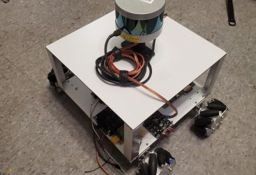
To house all the electronics, I found this nice steel enclosere, into which I (painstakingly) drilled a bunch of holes, and cut out a circle to accomodate a fan. The fan was necessary, since I was really pushing the stepper drivers to their limits by using such large moors for all the axes. Without it, they would quickly overheat form the power they were dissipating.


And with that, the mechanical build was complete (for now).
Now for the hard part.
Software
You may notice from the equations of motion that movement in CoreXY is not as simple as one motor per axis. In fact, in this arrangement, each motor moves the gantry in two axes at once, on a 45 degree diagonal. We have to carefully mix the rotations of both motors to vector the gantry to move how we want. In addition, these movements would have to occur simultaneously and synchronously in order to move from point A to point B in a straight line.
I used the TeensyStep library to help me control the synchronous movements of the motors and the velocity/acceleration profiles and created a large state machine for various parts of the game play. Check out the code on github below:
Testing and Finishing Touches
I mounted the finished device up on a wall with the controller and power supplies below and wired everything together making sure it was as messy and un-traceable as possible (don’t do this).


I’ll break down the operation of the machine in more-or-less the order of the state machine in the code above.
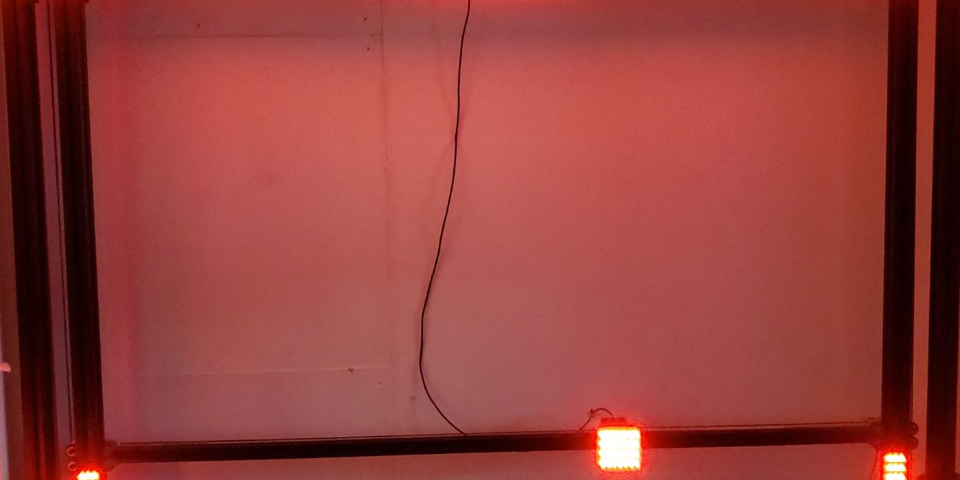
First up – Homing. In this state, All the LEDs are switched to red, and the machine slowly moves the ball toward the bottom left limits (i.e. max right and min down). This establishes where the machine is and allows me to define positions relative to that zero point.
The paddles don’t have limit swiches or a homing sequence yet and the machine just assumes they start all the way at the bottom. I do plan to put in limit switches for these too at some point.
Next the machine transitions to its Color Selection state. As the name implies, each player will at this point be allowed to select his/her paddle color. The X axis of the controller is used to scroll through the five available colors and pressing the Z button locks in the selection.
The paddle corresponding to the color being chosen is automatically raised to half height to indicate whose turn it is to choose their color.
After both players have chosen their color at the beginning of the game, the machine begins a countdown. This is a simple countdown from three displayed on the ball LEDs.
At the end of the countdown, the machine transitions to gameplay. The ball leds are switched to all white and the paddles are set to the color chosen in the earlier stage. To begin the game, the ball moves towards the right paddle to a randomized vertical position. If the right-side player manages to ‘hit’ the ball with their paddle (controlled via the controller’s Y-axis), the ball bounces off and heads toward the left paddle, with a final vertical position depending on where on the right paddle it hit. The game continues in this manner until one of the players misses the ball. If a player misses, a point is awarded to the other player, which is indicated on the ‘scoreboard’ row of LEDs at the top of the machine.
To determine whether the ball was hit or missed by the player paddles, I use relative positioning of paddle and ball elements by keeping track of the number of steps commanded to the motors and using that number to estimate the position based on the game elements’ starting home location. I can do this because I’m using stepper motors and assuming I built the rest of the machine correctly, one step commanded to the motor should result in one step in the game element in real life. Unfortunately, using this kind of positioning means that if I ever loose steps in one of the elements, for example by colliding with the physical limit of one of the paddles (remember I still haven’t put limit switches on these), my count of where that element is will be off and so the ‘hitboxes’ wont necessarily line up. Obviously, an encoder would do a lot of good here.
After a player scores, the machine enters a restore state. Here, the ball LEDs turn red and the ball is moved back to the center of the board, and new round is started beginning once again with a count down.
This restore->countdown->gameplay sequence is repeated until one of the players reaches a score of 10. The machine then, instead of going into the restore state again, now enters either the Left Win or Right Win state, during which the ball is moved back to the center, both paddles are automatically moved to the bottom of their travel, the winner’s paddle is raised to half height, and all LEDs on the board are flashed with the winners color.
At the end of this, both paddles are once again dropped and the machine returns to its homing state. At this point the whole game sequence is started anew.
Unfortunately, before I got a chance to finish everything up and finalize its installation in the lounge, we all got sent home in response to the coronavirus crisis. Hopefully, I’ll get the chance to come back and finish this project sometime soon.
Leave a Reply